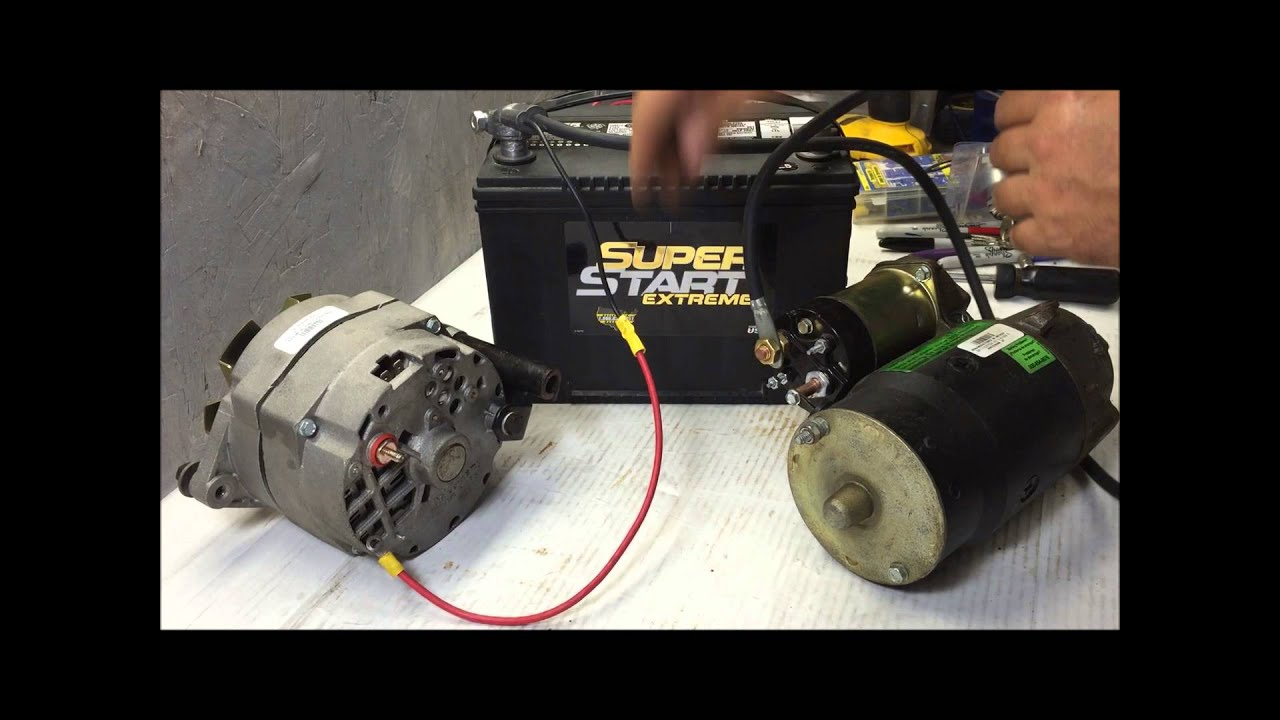
One Wire Alternator Diagram : one wire alternator install - YouTube / The original windings were 13 turns of.. This wire can also be terminated at the battery + terminal instead of the battery side of the starter switch. I figured this being my first foray into alternator rewinding, it would be much easier learning on a simple little 35amp alternator like this. The wiring varnish/shellac has sharp edges, so be careful when removing the old windings. The alternator requies no polarization process. We discuss the one wire alternator and the three wire alternator and the reasons you might choose a 1 wire over a 3 wire.
Here the basic internal circuit diagram of the car alternator and the wiring diagram of the alternator with battery is given below. Here is the wiring diagrams for the alternator so you can see how the system works with a guide to test the wiring as well. Power & control wiring trending. Tom moss goes out of his way to help people, and is a genuinely nice fellow. Because the ignition can get fed by the alt thru gahi's diagram is the correct way to wire a gm 10si/12si, and utilize all the benefits of that great design.
93 Gm Alternator Wire Diagram - Wiring Diagram Networks from www.pirate4x4.com 800 x 600 px, source: We discuss the one wire alternator and the three wire alternator and the reasons you might choose a 1 wire over a 3 wire. Electrical schematic & wiring diagrams. Wiring diagrams ford one wire alternator conversion gm wires, size: The alternator requies no polarization process. Floralfrocks.me below are several of the leading drawings we obtain from numerous sources, we really hope these photos will work to you, and also ideally very relevant to just what you desire concerning. You can find the correct one according to your car model as well as model year. Tom moss goes out of his way to help people, and is a genuinely nice fellow.
The wiring in my pickup truck was bad and mostly missing from a body swap and i converted to carb from tbi.
Connect wires one at a time to see what lead is drawing current. We discuss the one wire alternator and the three wire alternator and the reasons you might choose a 1 wire over a 3 wire. This battery bank in turn supplies the needed 12v input for the 110v inverter(s) which can. This component primarily consists of coils of wire that are large enough to carry the. Adding all three together produces the total ac. I'll start off with the caution. Wiring diagrams are highly in use in circuit manufacturing or other electronic devices projects. The layout facilitates communication between electrical engineers designing electrical circuits and. Electrical schematics, wiring diagrams, alternator identification information, and more can be found in this vanguard faq. The alternator, as the name implies, produces an alternating current (ac) output, which is rectified to direct current (dc) to provide the correct type of voltage to replenish the battery, to keep it at full charge. Again, always consult the wiring diagram—some airplanes don't have overvoltage sensors at all, and some overvoltage sensors are incorporated into. These are the wiring diagrams for that vehicle and both show that it has a fusible link (a111 dark. 800 x 600 px, source:
This battery bank in turn supplies the needed 12v input for the 110v inverter(s) which can. Searching for details about 1 wire alternator wiring diagram? The wiring in my pickup truck was bad and mostly missing from a body swap and i converted to carb from tbi. Moss's website, which i find much more useful than other sources. The car alternator has some circuitry inside it.
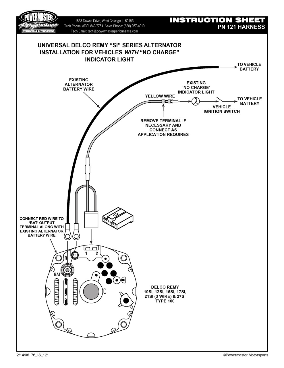
Powermaster 1 to 3 Wire Alternator Wiring Harness - SO-CAL ... from cdn11.bigcommerce.com We discuss the one wire alternator and the three wire alternator and the reasons you might choose a 1 wire over a 3 wire. This battery bank in turn supplies the needed 12v input for the 110v inverter(s) which can. To do this, a wiring diagram for the equipment is essential. When working properly, the three windings produce three currents that make up the three phases. I had trouble finding a diagram or any vide. The alternator requies no polarization process. Electrical schematics, wiring diagrams, alternator identification information, and more can be found in this vanguard faq. This wire can also be terminated at the battery + terminal instead of the battery side of the starter switch.
The field wire is the output to the alternator rotor, and the ground wire goes to ground under one of the mounting fasteners for the voltage regulator.
Does anyone know the wire colors? I figured this being my first foray into alternator rewinding, it would be much easier learning on a simple little 35amp alternator like this. Briggs & stratton supplies electrical components pertaining to the engine only. The layout facilitates communication between electrical engineers designing electrical circuits and. Diagram of a simple alternator with a rotating magnetic core (rotor) and stationary wire (stator) also showing the current induced in the stator by the rotating magnetic field of the rotor. Wiring diagrams ford one wire alternator conversion gm wires, size: These are the wiring diagrams for that vehicle and both show that it has a fusible link (a111 dark. Moss's website, which i find much more useful than other sources. 1,057 one wire alternator products are offered for sale by suppliers on alibaba.com, of which diesel generators accounts for 15%, car alternator there are 257 suppliers who sells one wire alternator on alibaba.com, mainly located in asia. Floralfrocks.me below are several of the leading drawings we obtain from numerous sources, we really hope these photos will work to you, and also ideally very relevant to just what you desire concerning. Here is the wiring diagrams for the alternator so you can see how the system works with a guide to test the wiring as well. Connect wires one at a time to see what lead is drawing current. Searching for details about 1 wire alternator wiring diagram?
Once the voltage regulator turns on. 1,057 one wire alternator products are offered for sale by suppliers on alibaba.com, of which diesel generators accounts for 15%, car alternator there are 257 suppliers who sells one wire alternator on alibaba.com, mainly located in asia. Moss's website, which i find much more useful than other sources. Wiring diagrams are highly in use in circuit manufacturing or other electronic devices projects. This is the speed where the internal sensory circuit connects the battery voltage to the regulator, thereby turning the alternator on.
Basic Gm Alternator Wiring | Best Wiring Library - Gm 1 ... from 2020cadillac.com This wire can also be terminated at the battery + terminal instead of the battery side of the starter switch. When the rotor rotates, the stator conductors which are static in case of alternator cut by magnetic flux , they have induced emf produced in them (according to faraday's law of electromagnetic induction which. Connect wires one at a time to see what lead is drawing current. The original windings were 13 turns of. There are many types of wiring diagram for different types of alternators. Again, always consult the wiring diagram—some airplanes don't have overvoltage sensors at all, and some overvoltage sensors are incorporated into. The diagrams above show how to wire the system, starting with the 12v generator made with the automotive alternator, going to the battery bank to keep it charged. The field current, approximately six to eight amps, energizes the rotor which then induces an electric.
My case manual does not show the wiring diagram for a 580ck with an alternator.
Adding all three together produces the total ac. To do this, a wiring diagram for the equipment is essential. You can find the correct one according to your car model as well as model year. Moss's website, which i find much more useful than other sources. Briggs & stratton supplies electrical components pertaining to the engine only. 1 phase & 3 phase wiring. I had trouble finding a diagram or any vide. 800 x 600 px, source: This component primarily consists of coils of wire that are large enough to carry the. The field current, approximately six to eight amps, energizes the rotor which then induces an electric. Green ten gauge) spliced to the black with gray wire that goes to the. Again, always consult the wiring diagram—some airplanes don't have overvoltage sensors at all, and some overvoltage sensors are incorporated into. One is to energize the field, i think the other is stator, would need to look at a diagram.