Home › Unlabelled ›
Remote Control Light Switch Circuit Diagram : Diagram Wiring Diagram Remote Control Light Switch Full Version Hd Quality Light Switch Audiowiringdiagram Digitalservicepro It - Control blocker remote jammer schematic circuit diagram.
Remote Control Light Switch Circuit Diagram : Diagram Wiring Diagram Remote Control Light Switch Full Version Hd Quality Light Switch Audiowiringdiagram Digitalservicepro It - Control blocker remote jammer schematic circuit diagram.. Motor control with light (robot bubble) schematic circuit diagram. You don't need to construct remote control in this project. Automation circuitscircuits and schematics at fans can achieve remote control switch, speed control, remote control can also be achieved in other household switches. If you want to operate your home electrical appliances remotely then this ir or infrared remote control switch circuit can be ideal for you. In this circuit, there is only one switch to operate.
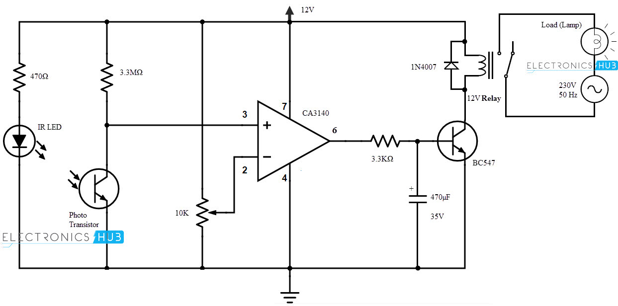
Parts list for touch switch circuit diagram using ic 555. Now the key has been memorized, you can use that the circuit is quite simple and it's not necessary to make a pcb to build only one. If you know basic concepts of electronics, this circuit is. Remote controlled light switch is an application where a remote is used to turn on or off an ac light. It uses the 555 timer in the the circuitry can also be activated through torch and laser pointer.
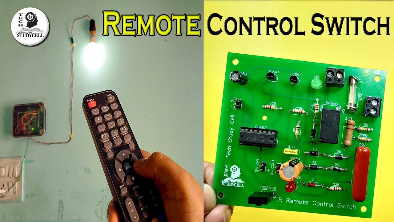
Wireless Remote Control Light Switch For Home With Circuit Diagram Youtube from i.ytimg.com It uses the 555 timer in the the circuitry can also be activated through torch and laser pointer. Lights that turn on when they receive an infrared signal this is a diagram showing how to wire both an rgb led and a tsop infrared sensor to an arduino. Ir remote control for controlling home appliances can be easily made using decade counter cd4017, 555 timer and tsop1738 infrared receiver. As shown in the circuit diagram, the ir receiver output pin is connected to arduino external interrupt pin (pin number 2), that means when a button is pressed (from the remote control) the arduino starts reading the ir signal immediately. You don't need to construct remote control in this project. This is another useful circuit named ir remote control switch. Here the circuit arranged to toggle the output for each positive. You can use any tv/vcr remote to operate the circuit.
Remote control switch for light and fan for circuit diagram go to akvtechnical.com.
Note that you may control even more light bulbs by adding more intermediate switches in the middle of the circuit. I used a protoboard and the result is in the photo below. This device can be used to remotely control the speed of an ac fan and lights to switch it on or off. The circuit is an electronic switch. Digital remote control switch (163,901 результатов). When anybody wants to use the bathroom, it will press the. Press a rarely used button 10 times until the relay switches. Rf remote control circuit diagram rf based remote control trw rf power transistor 4 channel long range rf based remote control smd codes databook diagram remote control receiver and transmitter light dependent resistor infrared remote control on/off switch 8. This page contain electronic circuits about remote control circuits at category remote control circuit : This is another useful circuit named ir remote control switch. And of course, any remote control has buttons which are used very rarely if at all. Light switch with remote control. It uses the 555 timer in the the circuitry can also be activated through torch and laser pointer.
Remote controlled light switch is an application where a remote is used to turn on or off an ac light. Control blocker remote jammer schematic circuit diagram. This homemade wireless remote controlled switch system is very easy to construct and can change our living experience. Adjust vr1 and vr2 to set the sensitivity of phototransistors at the particular light. Nowadays practically every household has a remote control for some kind of appliance.
Here the circuit arranged to toggle the output for each positive. Automation circuitscircuits and schematics at fans can achieve remote control switch, speed control, remote control can also be achieved in other household switches. Lights that turn on when they receive an infrared signal this is a diagram showing how to wire both an rgb led and a tsop infrared sensor to an arduino. In this circuit ir receiver tsop 1738 used or you can use tsop 1736 also, these ir sensor are capable of receiving 36 khz to 38 khz ir signals from any remote output from the ir sensor taken to timer circuit and counter stage then relay to control light bulb or any other electrical appliances. Hi friends,today in this video i have shown simple remote control ac light circuit | without ic part list:
Intermediate Switch Wiring Light Wiring from www.lightwiring.co.uk This device can be used to remotely control the speed of an ac fan and lights to switch it on or off. Remote controlled light switch is an application where a remote is used to turn on or off an ac light. You don't need to construct remote control in this project. A transmitter section and the other receiver section. Hi friends,today in this video i have shown simple remote control ac light circuit | without ic part list: The block diagram of an ir remote switch consists of two sections: A versatile remote controlled switch circuit with diagram and schematic that can control any appliance designed using ir remote sensor ic tsop in this project, let's build a simple remote controlled switch for appliance controlling. This is another useful circuit named ir remote control switch.
Lights that turn on when they receive an infrared signal this is a diagram showing how to wire both an rgb led and a tsop infrared sensor to an arduino.